
Tool Data Sheet

This tutorial will guide you through the contents of the ToolsUnited tool data sheet. You will learn where to find key information, how the different sections are organized, and how to make effective use of the available features and functionalities.

Watch the How-To Video

Watch the tutorial to gain a better understanding of the workflow and available functionalities.

Follow the Step-by-Step Guide

Everything you need to know, explained step by step.
1

Tool Data Sheet

The tool data sheet is divided into three sections: Overview, Graphic Generator, and Accessories.

2

Overview

The Overview tab is the main workspace and consists of several sections:

3

Header

Here you will find general information about the tool as well as available actions for working with the tool data:

  • Assemble complete tool – opens the complete tool editor
  • Matching components – searches for compatible components (e.g., holders or cutting inserts)
  • Copy & edit – creates an editable copy of the tool (e.g., for custom-made special designs)
  • Data export – exports tool data to your target system (e.g., CAM)
  • Configurable export – customizes which data is exported
  • Tool basket – collects tools and accessories for later batch download
  • Send feedback – direct contact with the ToolsUnited team
  • Print – creates a print-optimized version
  • Buy tool – displays available suppliers/dealers
4

Graphics section

Here are all the available graphics for the tool

  • Tool class graphic – describes the type and geometry (DIN or ISO/GTC)
  • Manufacturer graphics – images, drawings, and 3D models
  • Generated 3D graphics – automatically generated CAD model based on geometry data and CIMSOURCE tool models (updates automatically when changes are made – unlike static manufacturer graphics)
5

Geometric data

The following table lists all geometric features for the tool:
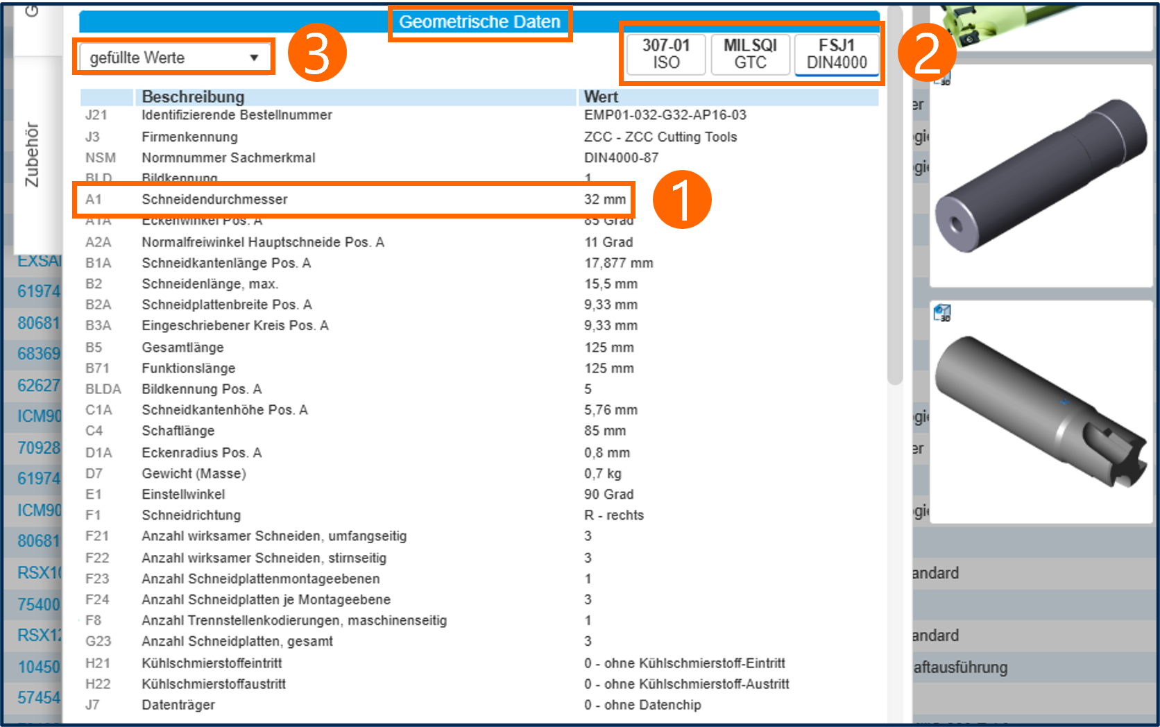
  1. Each feature consists of an abbreviation, a description, and a value
  2. Display options include DIN or ISO/GTC
  3. Filter using the dropdown menu (e.g., populated values or features relevant for 3D modeling)
6

Working process

This list includes all the manufacturing processes for which the tool is suitable.

7

Connection codes

The following is a list of all the interfaces available for this tool:

  • Interfaces are defined according to industry standards and/or manufacturer specifications
  • Distinction between machine-side (e.g., holder) and workpiece-side (e.g., cutting insert) – depending on the tool type
  • Basis for finding the right components in ToolsUnited
8

Speeds & Feeds

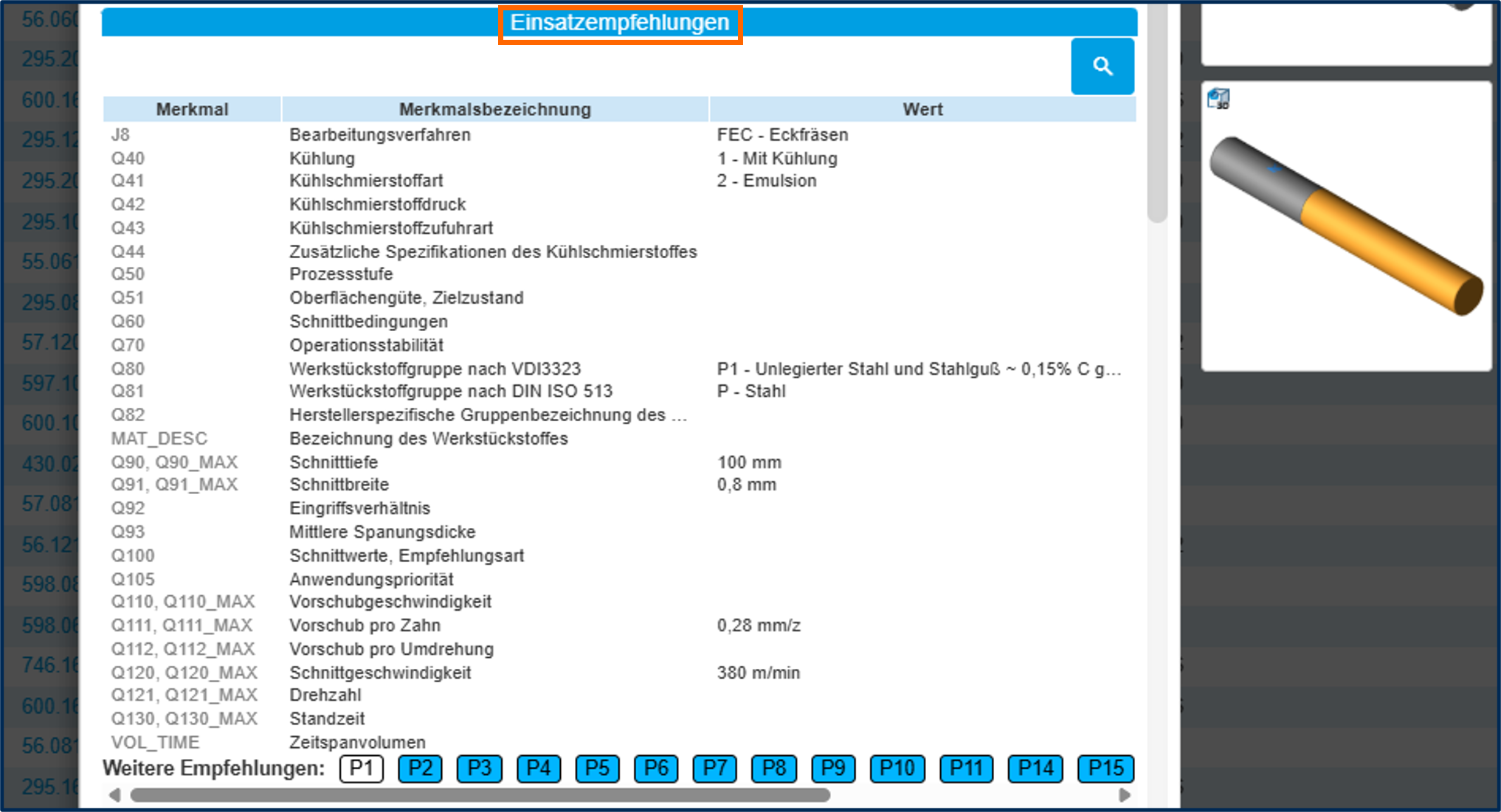
The following table lists the recommended process parameters based on the specific material.
9

Order data

Here is all the relevant information regarding tool purchasing.

10

Similar tools

Here are similar tools from the same manufacturer.

11

Graphic generator

You can download graphics and tool data in standardized formats from this section.

12

Accessories

Displays available accessories for the selected tool within ToolsUnited.