
If you work with turning tool holders for indexable inserts, this article is for you.
Here’s a challenge for you: how would you define the functional height in the different sketches below? There are multiple ways, and that’s the problem.
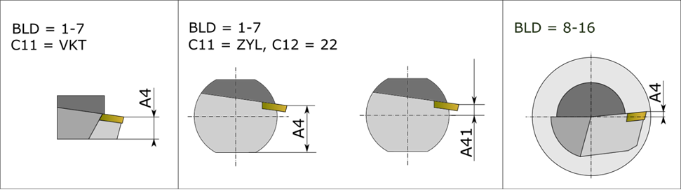
In DIN 4000-90, A4 is the functional height used in digital toolholder descriptions.
A new A41 is the solution that the Technical Working Group (TWG) proposes. With the new A41, the cutting edge is always measured from the shank axis – no guessing in data exchange, CAM etc.
- A4: keeps its historical meaning as functional height in DIN (from DIN 4000-90:2011-12) – reference from the bottom flat surface of the shank to the cutting reference point of the insert.
- A41: Proposed new, consistent definition – measured from shank-axis (Z-axis) to the cutting reference point.
- A41 aligns with functional height (HF) in ISO terminology.
Why this matters: cleaner, axis-based geometry for CAM, less remapping between DIN and ISO, and more predictable collision checks and simulation models – especially for round shanks and tool heads.
Good to Know – Even Better to Use
The topics in discussion are not just technical nuances – they reflect strategic groundwork for anyone working with digital tools. Understanding these updates ensures your systems, processes, and products stay compatible, competitive and clean.
What’s next?
On 2–3 December 2025, the DIN committee will meet in Dresden to discuss the first working papers for a possible revision of DIN 4000/4003-90. We’ll be there and report back on the outcome.
Until then, we’d like to hear from you: if you rely on DIN 4000-90 data in catalogues, CAM interfaces or 3D generators, how should A4 and A41 work in your environment? Your feedback helps us bring real-world use cases into the discussion.